Contents
Required tools
Go to Resources for download links.
- Blender
- SuperBMD
- j3dview
- Any text editor you like (Notepad++ is recommended)
- NeoKCLCreate
- Arc Convertor
- Whitehole
- Wiimm's ISO Tools (to get your SMG1 dump)
Required tutorials
- How to import a custom model into SMG1
- How to import a custom model into SMG1 with 1 in-game material
- How to import a custom model into SMG1 with 2 or more in-game materials
Steps --- files used: tutorial5.zip
In this tutorial I will show you how to make a custom model that works with several in-game materials that when combined generate a certain overall effect, a nice looking ice effect. The object containing that ice visual effect, which will be used as a reference for our custom model, is found in SMG1. It is the IceRingIcePlanet object from the IceVolcanoGalaxy (Fig. 1).
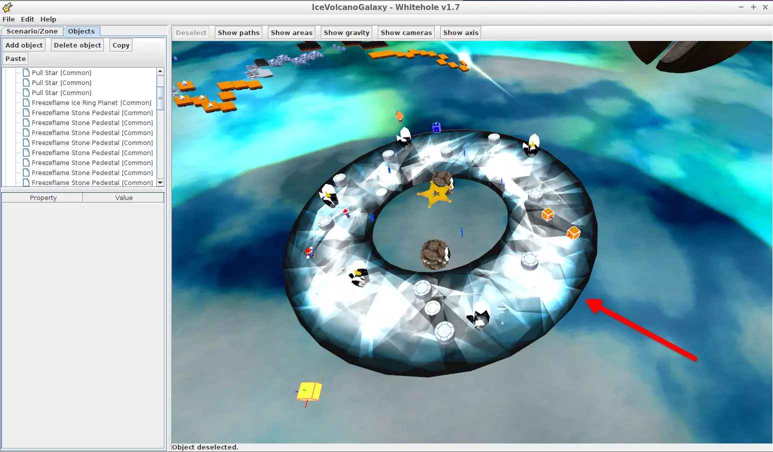
(Fig. 1 - IceRingIcePlanet object)
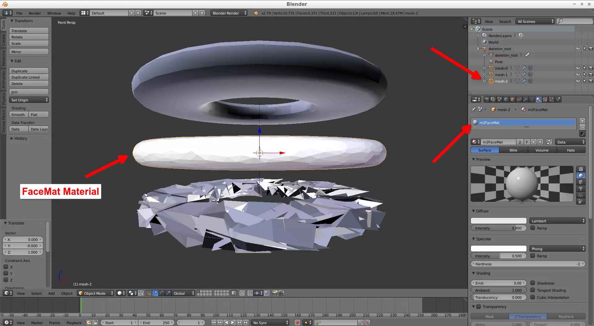
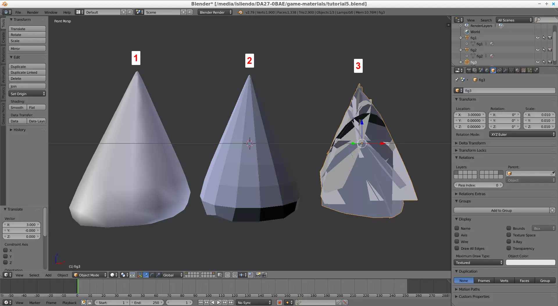
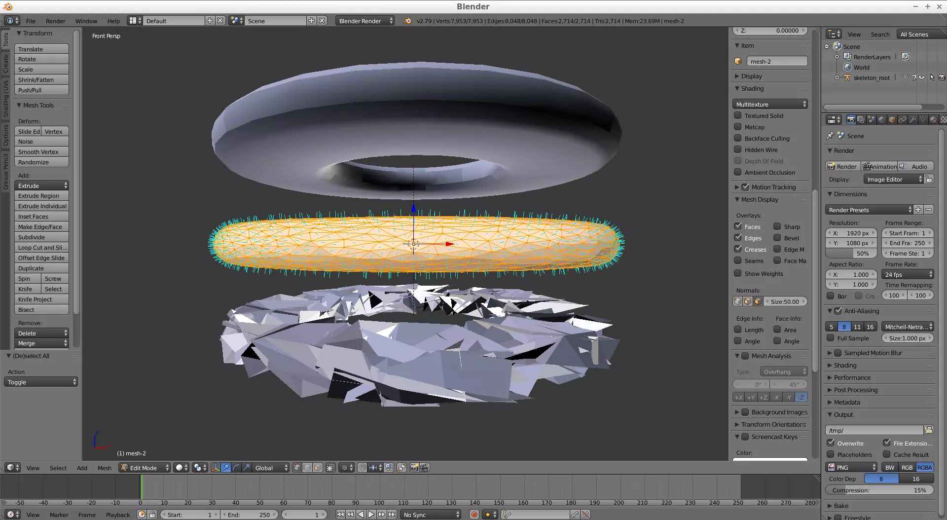
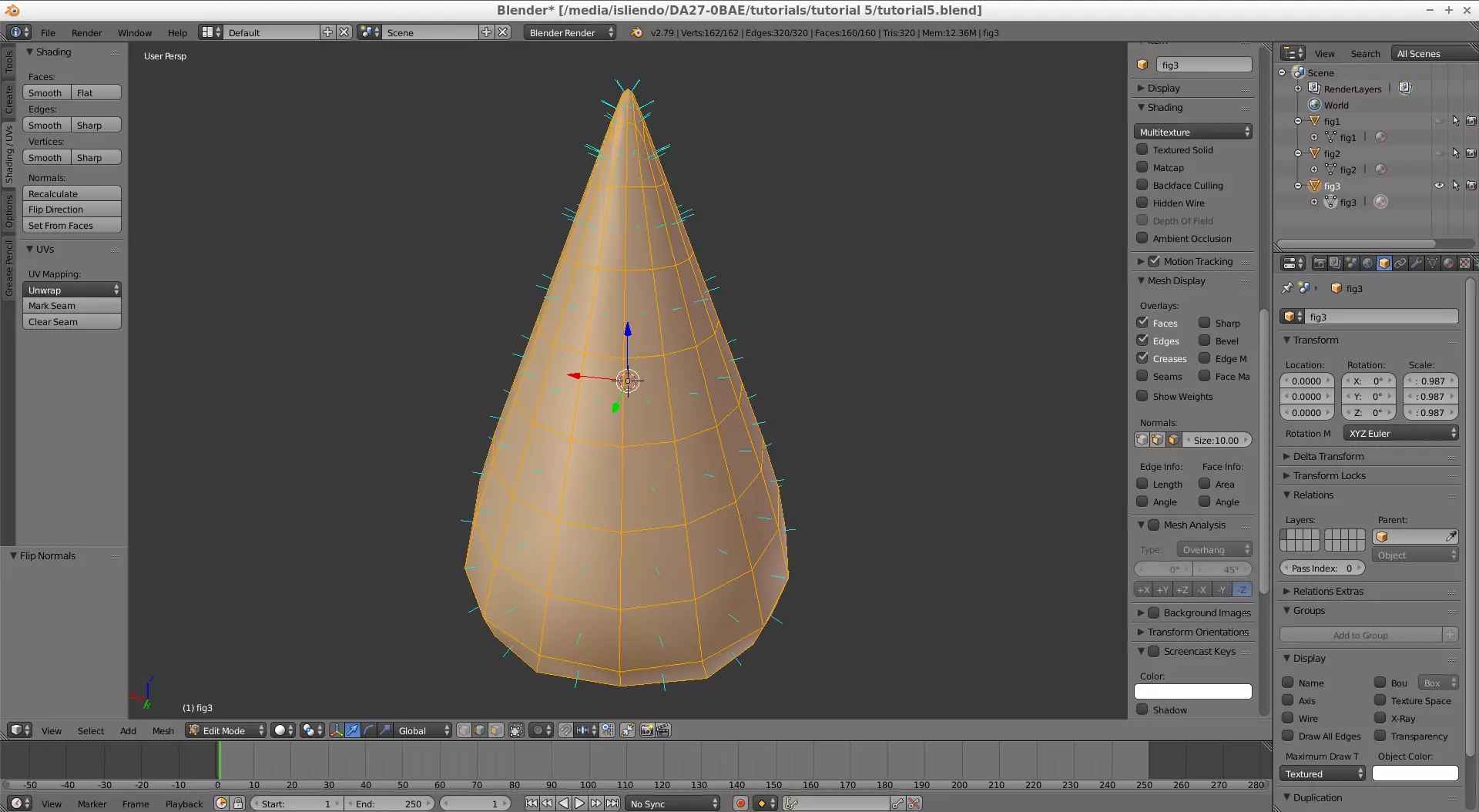
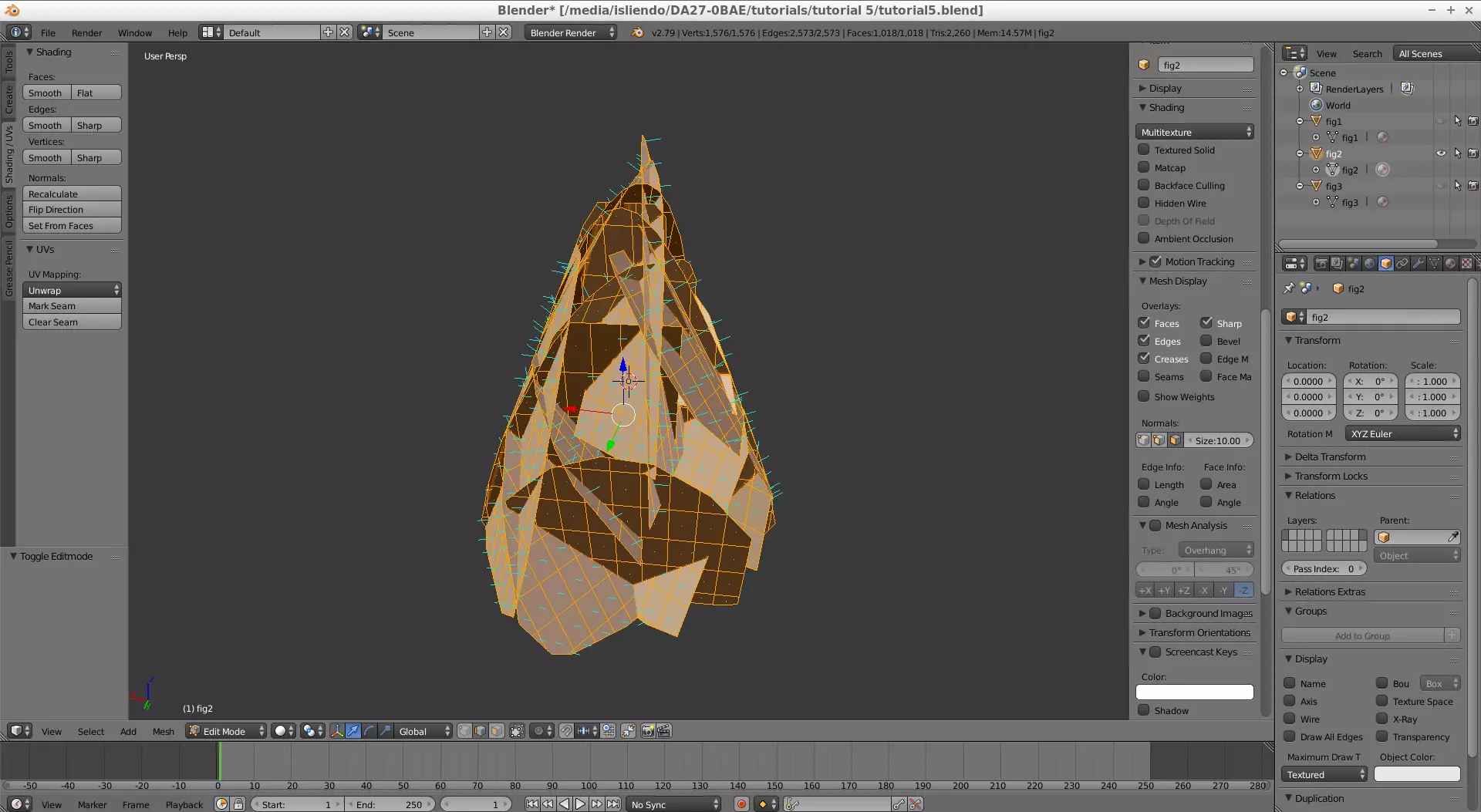
Extract the contents of the ARC file of the model, and extract the contents of the BDL file. Then, open with Blender the DAE file created by SuperBMD (Fig. 2). As you can see, this object is divided in 3 pieces, one inside another and there is a single material applied to each part (Fig. 3a, 3b and 3c).
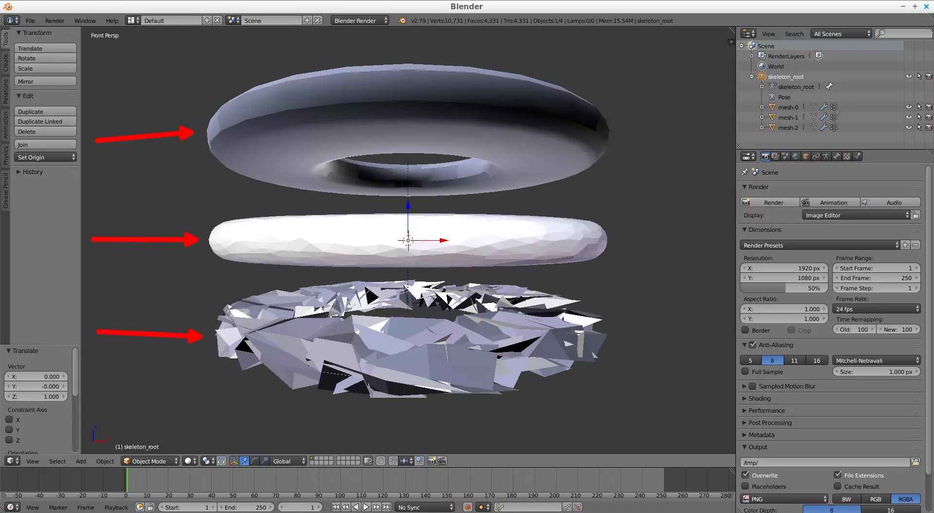
(Fig. 2 - Figures composing the IceRingIcePlanet object)
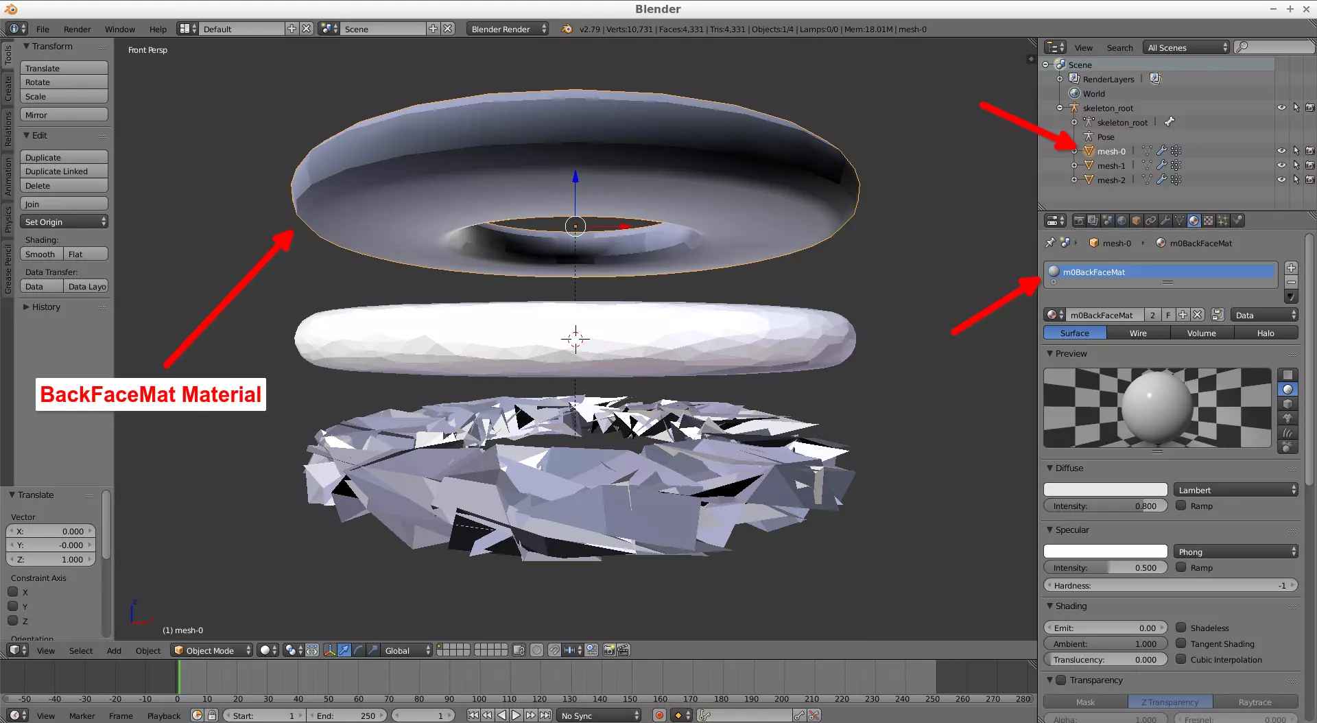
(Fig. 3a)
(Fig. 3b)
(Fig. 3c)
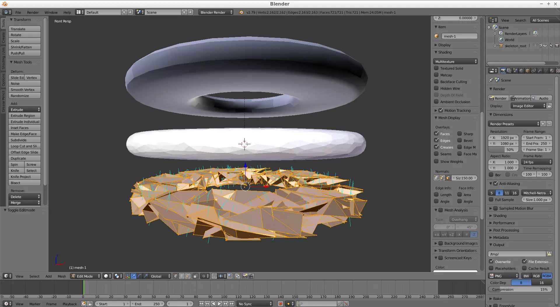
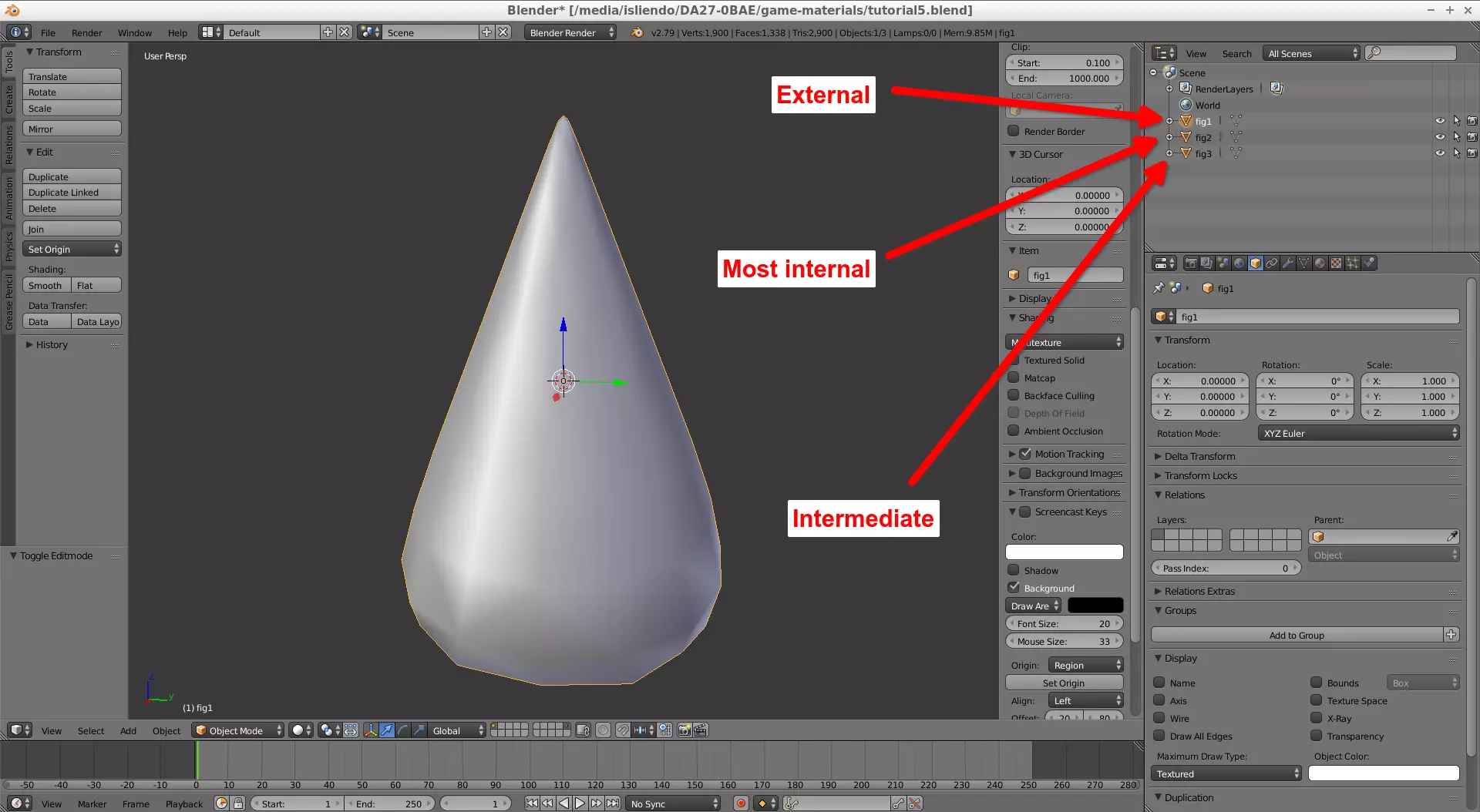
It is the combination of these 3 figures with these 3 materials that makes it so this object looks like it is made of a ice (a very complex ice), so, the custom model we want to make containing this ice effect must be modeled in a way that imitates the shape of this object. Our ice model must be divided in 3 pieces: an external figure, an intermediate figure and a figure that is contained in both figures (Fig. 4).
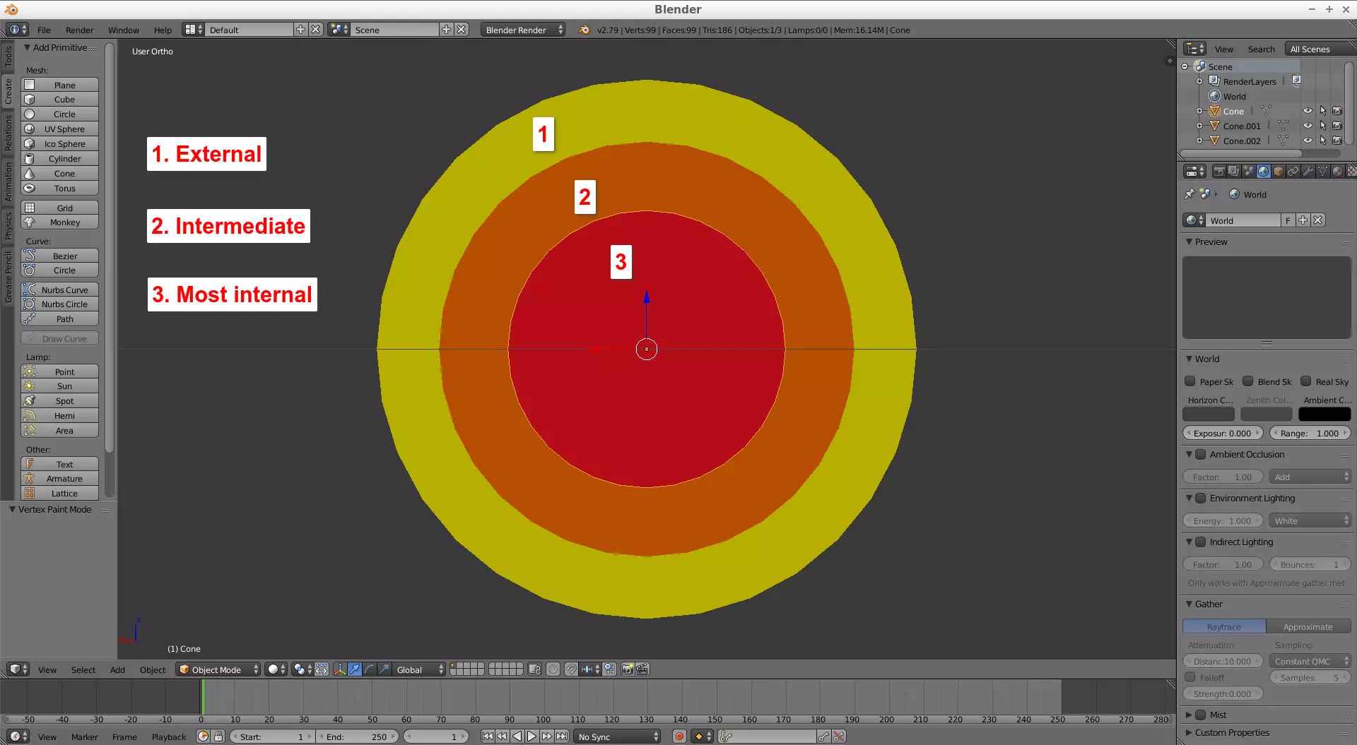
(Fig. 4 - Example figure)
I decided to make a stalactite-type model in (Fig. 5). The external and intermediate objects were shaped almost the same on the IceRingIcePlanet model so I made those on my model look the same, I just scaled them a little bit to put one inside another (they were made out of a cube --> Link). And the object inside both figures was made using Particle Effects (Link) using planes (as the particles) and the Boolean Modifier on another Blender project so no dumb stuff happens on the main one (Link).
(Fig. 5 - Stalactite-type custom model pieces)
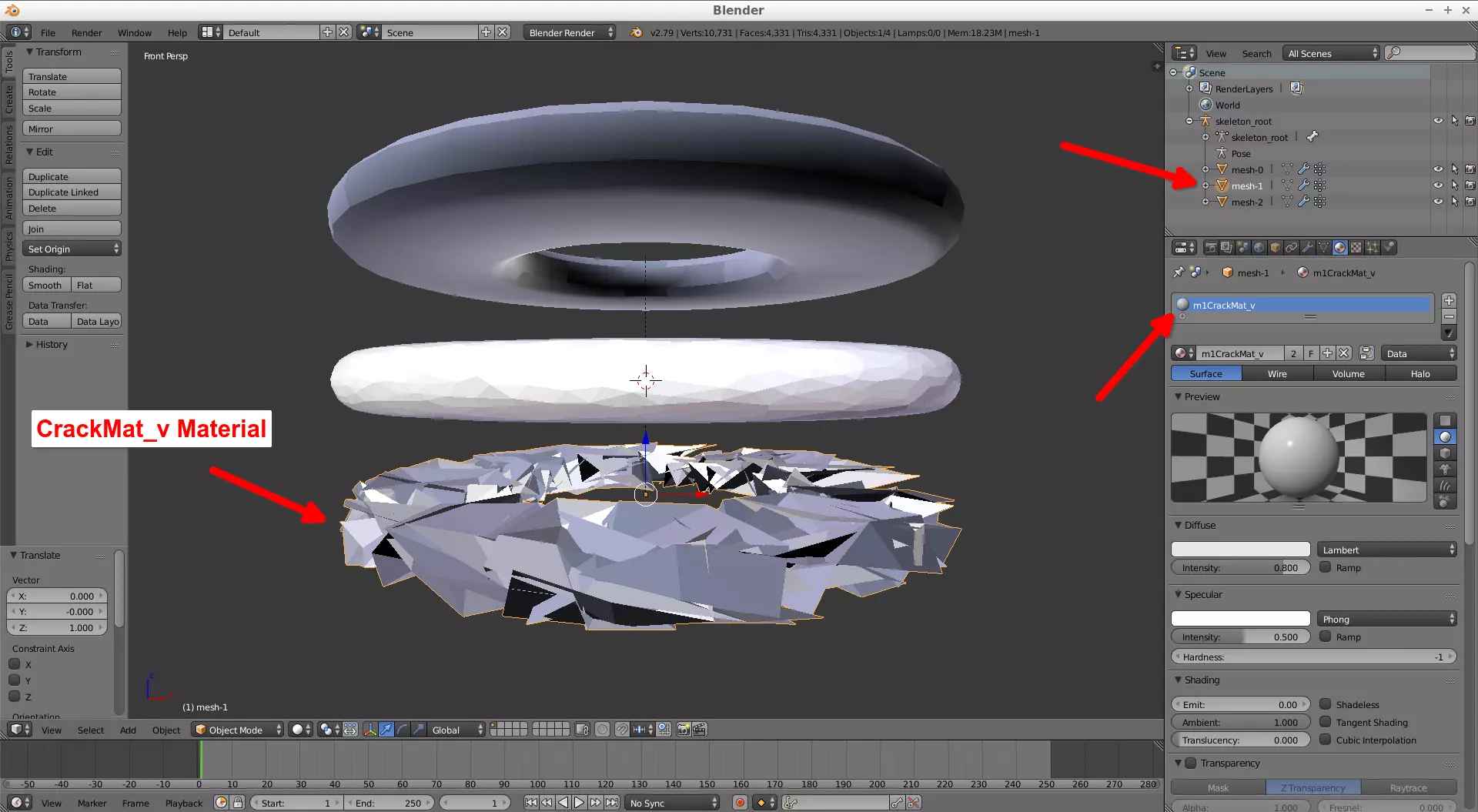
Apply the respective materials to each figure BackFaceMat for the external figure, FaceMat for the intermediate figure and CrackMat_v to the figure inside both figures (Fig. 6a, 6b and 6c). Remember to do the unwrap options. Use vertex paint and/or shade smooth as you like.
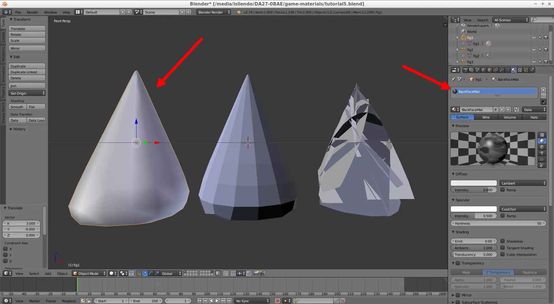
(Fig. 6a)
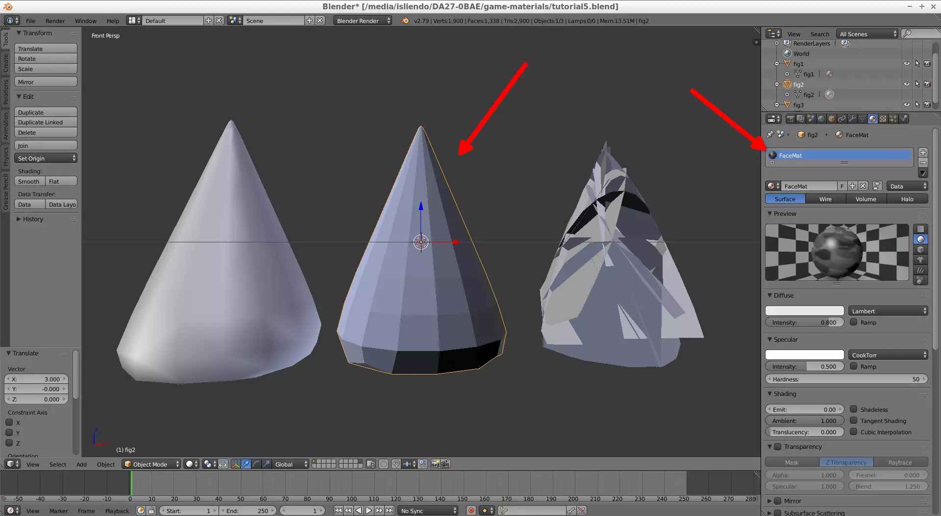
(Fig. 6b)
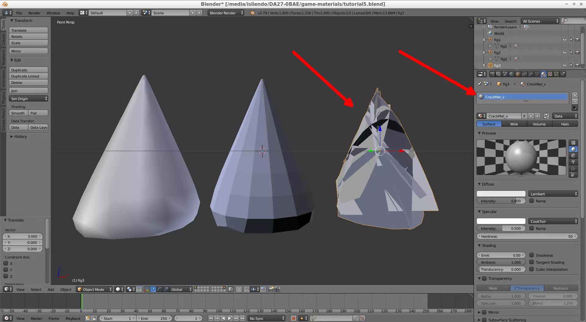
(Fig. 6c)
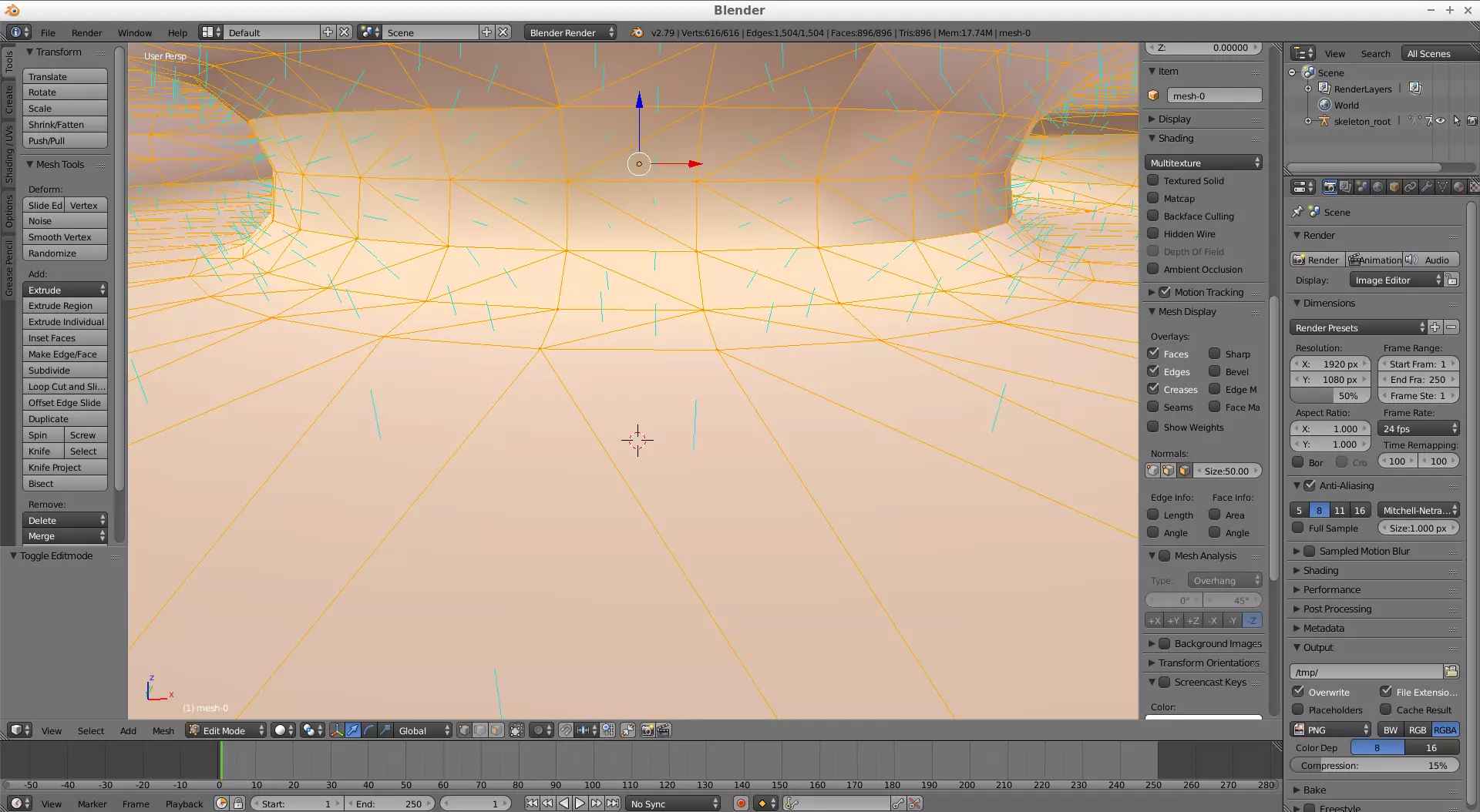
As we are dealing with materials inside materials we have to be careful with the normals of the faces, in other words, in which direction faces point in each figure: to the outside or the inside of the figure. This is because the visual effect on a material depends on the face direction. To view the normals of a figure hit the N key while being in Edit Mode selecting all faces on a figure, scroll down to Mesh Display and, in the Normals section, click on the face selection and set a size to the normals displayed (Fig. 7). To flip the orientation of the normals go to Shading / UV > Normals: > Flip Direction (be sure to select the whole figure in Edit Mode when doing this, Fig. 8). By default, when you create a figure in Blender, the normals will be set to the outside of the figure.
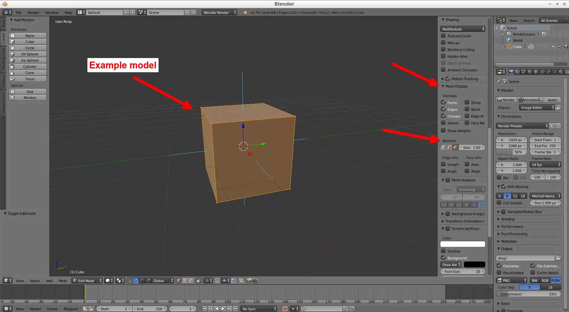
(Fig. 7 - Display normals in faces)
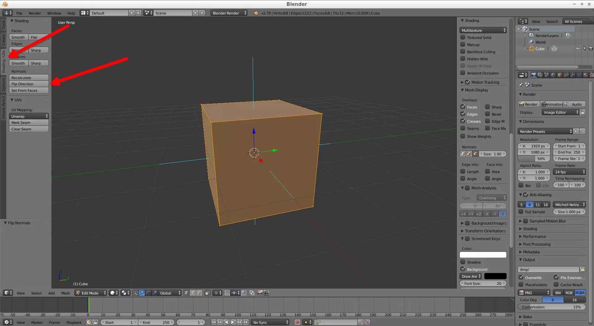
(Fig. 8 - Flip faces normals)
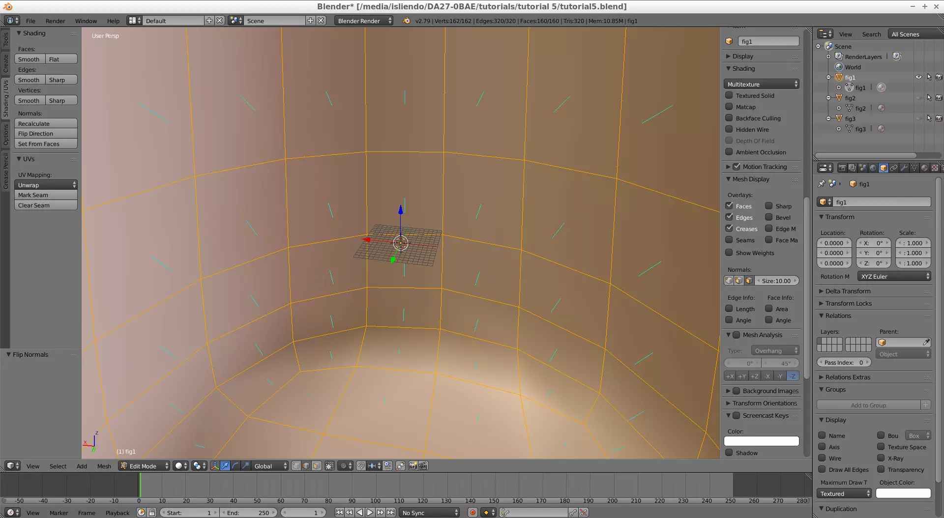
Back in the DAE model we can see that it has the faces for its external figure pointing inwards and the intermediate one pointing outwards (Figs. 9a, 9b and 9c).
(Fig. 9a - Normals in DAE external figure pointing inwards)
(Fig. 9b - Normals in DAE intermediate figure pointing outwards)
(Fig. 9c - Normals in DAE internal figure)
Then, for this ice effect setup we will follow the same face orientation each part of the respective DAE model has: normals on the external figure point inwards (Fig. 9d) and outwards on the intermediate part (Figs. 9e and 9f).
(Fig. 9d - Normals in custom model external figure pointing inwards)
(Fig. 9e - Normals in custom model intermediate figure pointing inwards)
(Fig. 9f - Normals in custom model internal figure)
NOTE 1: You can't actually tell to which direction the internal figure's faces point since it isn't a closed surface. Any direction will be fine so you can keep the default one Blender applies.
The final step will be ordering the objects on Blender (by changing their names) in the following way: the most external figure first, the figure inside both figures second and the intermediate figure third (as the order shown in the IceRingIcePlanet DAE model, Fig. 10). This is done because the order will affect how SuperBMD applies the materials to the custom model and consequently will affect the looks of the object in game.
(Fig. 10 - Name order respective to each figure)
Now, after all that, "compile" the model using SuperBMD using the --nosort option at the end of the command (IMPORTANT). This will ensure the proper material effect.
path\to\SuperBMD.exe [your_model].fbx --mat [your-materials].json --texheader [your-textures].json --rotate --nosort
NOTE 2: Linux users, remember to use a forward slash instead of a backslash for paths!
Now you can open the converted model file on j3dview, save it as BDL in a folder with the same name as the model, do the rest of the stuff to import the model in game and you will get what is shown on Fig. 11.
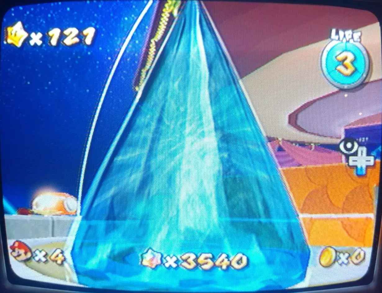
(Fig. 11 - Mario staring at some nice looking ice)
NOTE 3: Thanks to Zyphro for the guidence.