Contents
3. Pre-tutorial
4. Steps
Required tools
Refer to the "Resources" section for download.
- Blender
- SuperBMD
- j3dview
- j3d animation editor
- Any text editor you like (Notepad++ is recommended)
- Arc Convertor
- Whitehole
- Wiimm's ISO Tools (to get your SMG1 dump)
Required tutorials
- Basically all of the ones before this one.
Pre-tutorial
Before starting the tutorial I will teach you something you will need to know when using Blender to setup bones of an object for SMG.
First you need to know that when I refer to a bone I am referring to an Armature bone. Armatures by default have only 1 bone in Blender (Fig. 1).
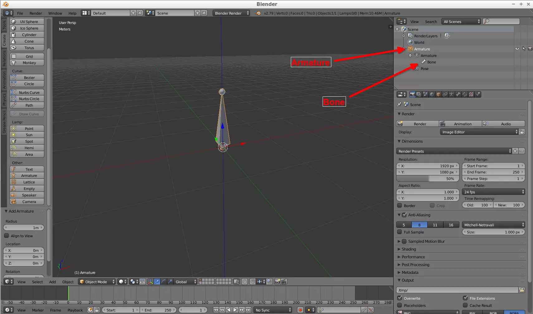
(Fig. 1 - Armature object)
To get (for example) more bones in an Armature, let's say 3, you can create 3 Armature objects (Fig. 2), select all of them and join them by pressing Ctrl + J, resulting in a 3 bone Armature object (Fig. 3). Alternatively, you can create a single Armature object, enter Edit Mode, and press Shift + A, that will create another bone in the Armature.
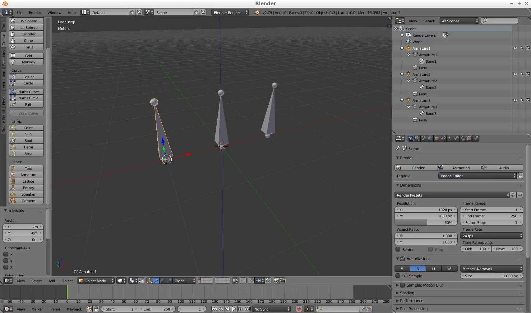
(Fig. 2 - 3 Armature objects)
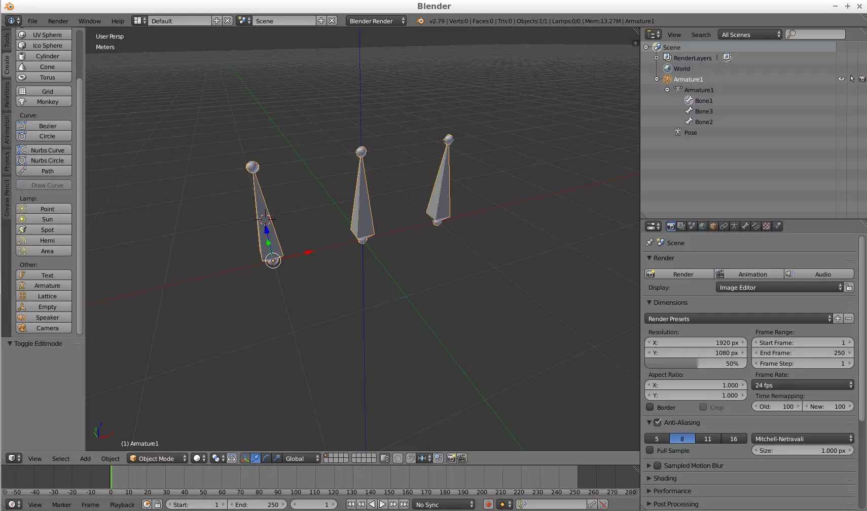
(Fig. 3 - Armature object with 3 bones)
Once they are joined the individual bones can be moved in Edit Mode (by selecting one of them). The name of each bone will highlight when clicked under edit mode (Fig. 4).
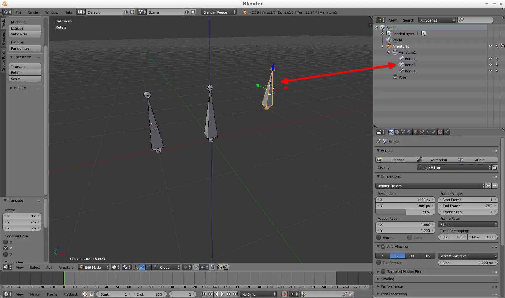
(Fig. 4 - Name of bone from armature)
With that clear, the next thing to do is to decide how to parent the bones (the child bones will inherit the animations of the parent bone). You can parent bones by selecting one and setting its parent by going to the Bone tab of a selected bone under Edit Mode (Fig. 5).
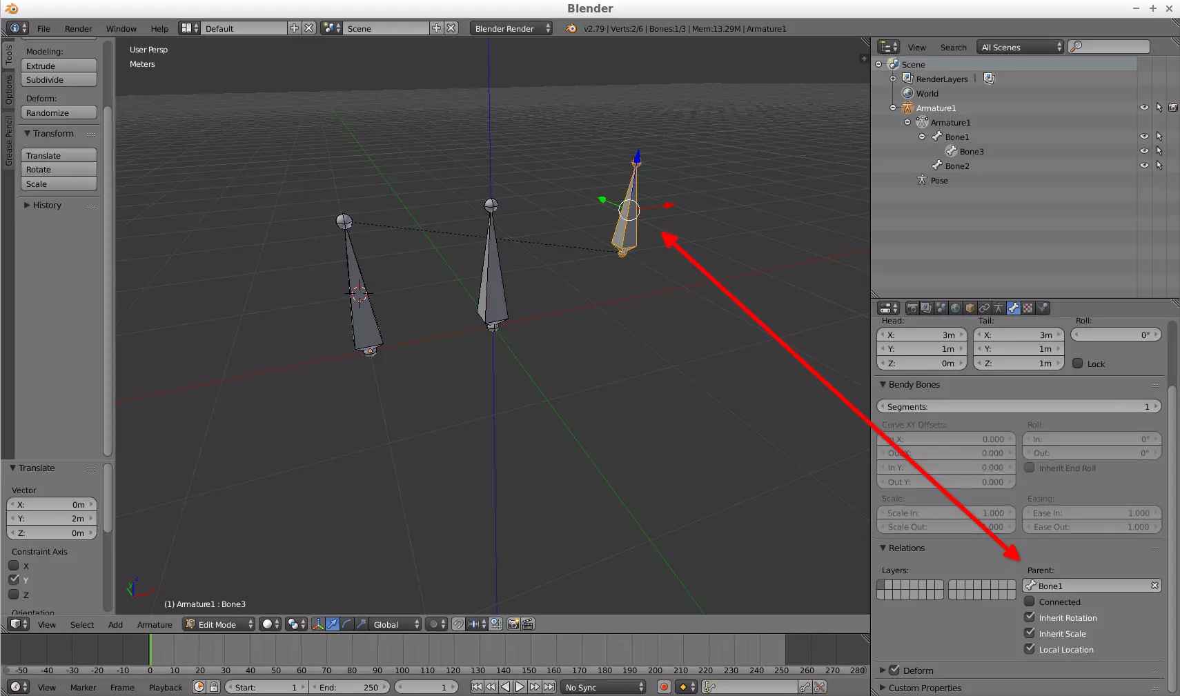
(Fig. 5 - Bone parenting)
You can decide from here what bones you want to parent and such (Fig. 6).
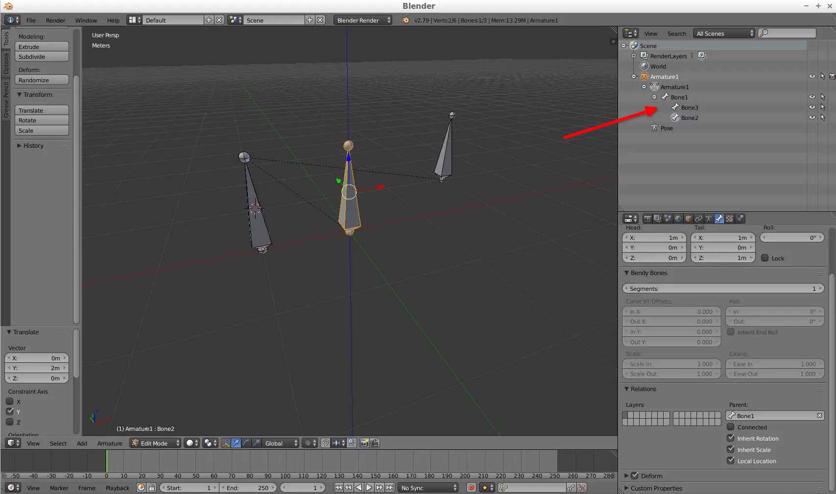
(Fig. 6 - Example of bone parenting)
Now, with that said, the way to link meshes (models) to these bones is to assign the mesh to a Vertex Group named exactly as the bone name and assign all its vertex (also part of its vertex is valid but that is for complex models) to that vertex group (Fig. 7 and 8). The mesh will be weighted when assigned to the vertex group so there is no need to manually weight it.
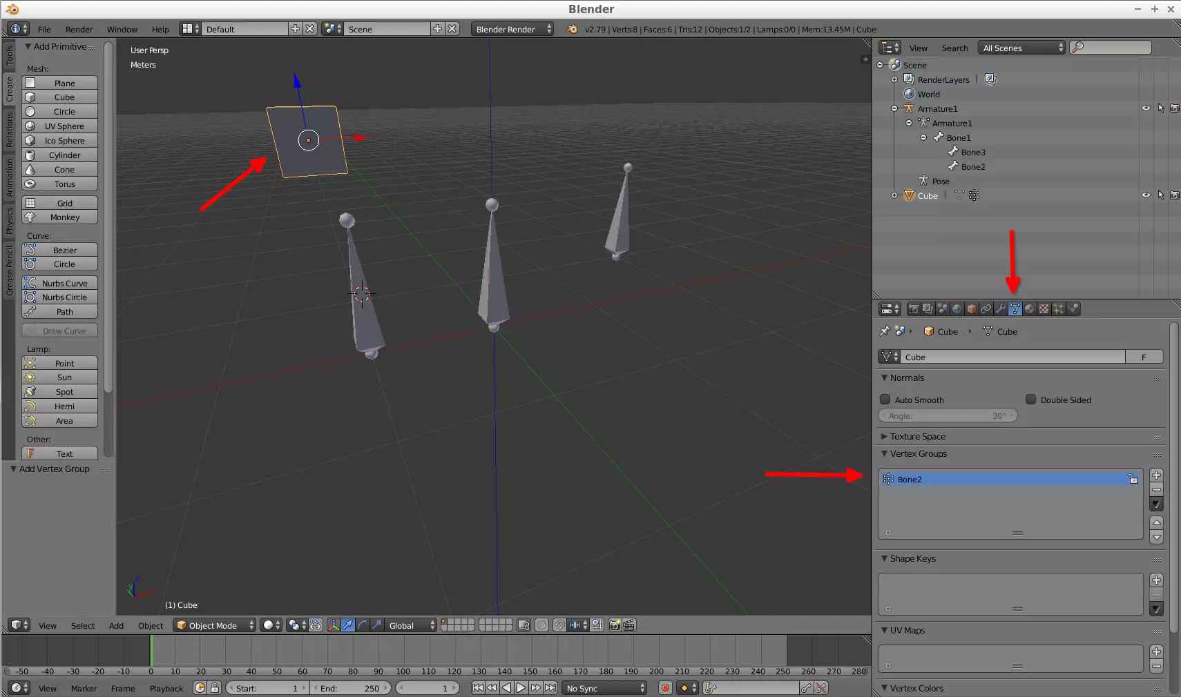
(Fig. 7 - Creating vertex group)
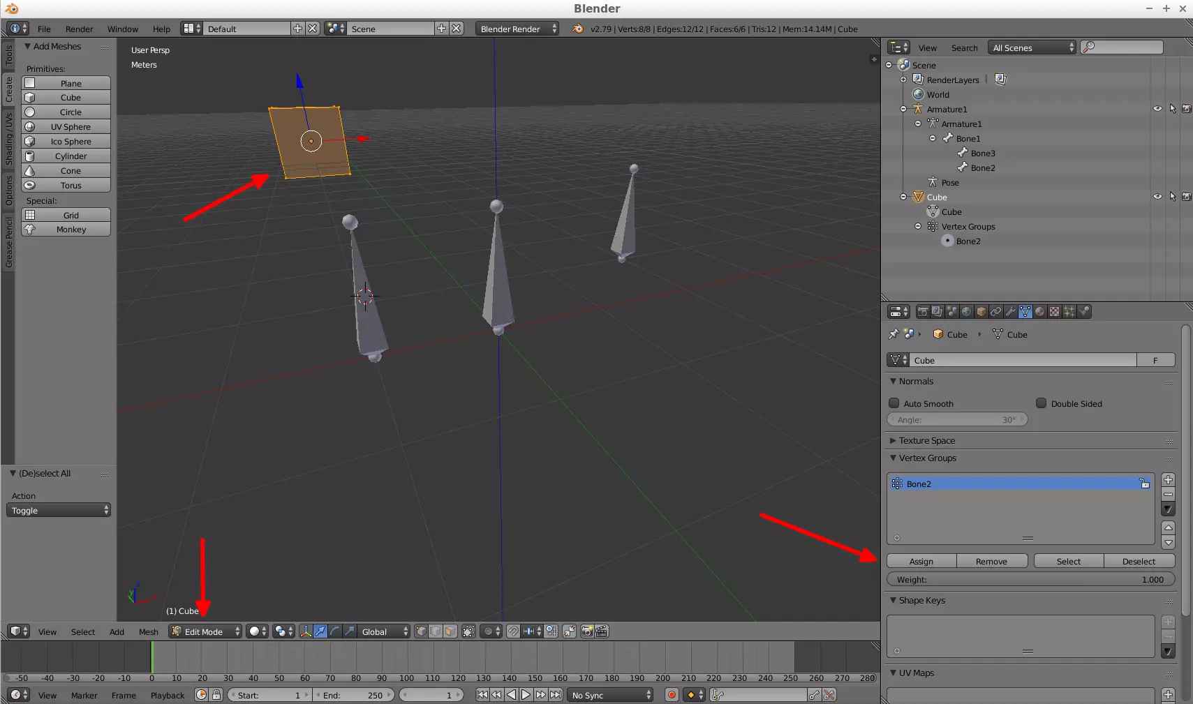
(Fig. 8 - Assigning vertex from mesh to vertex group)
Also, set an armature modifier for your mesh (model) and set the Object property to be the armature object (Fig. 9).
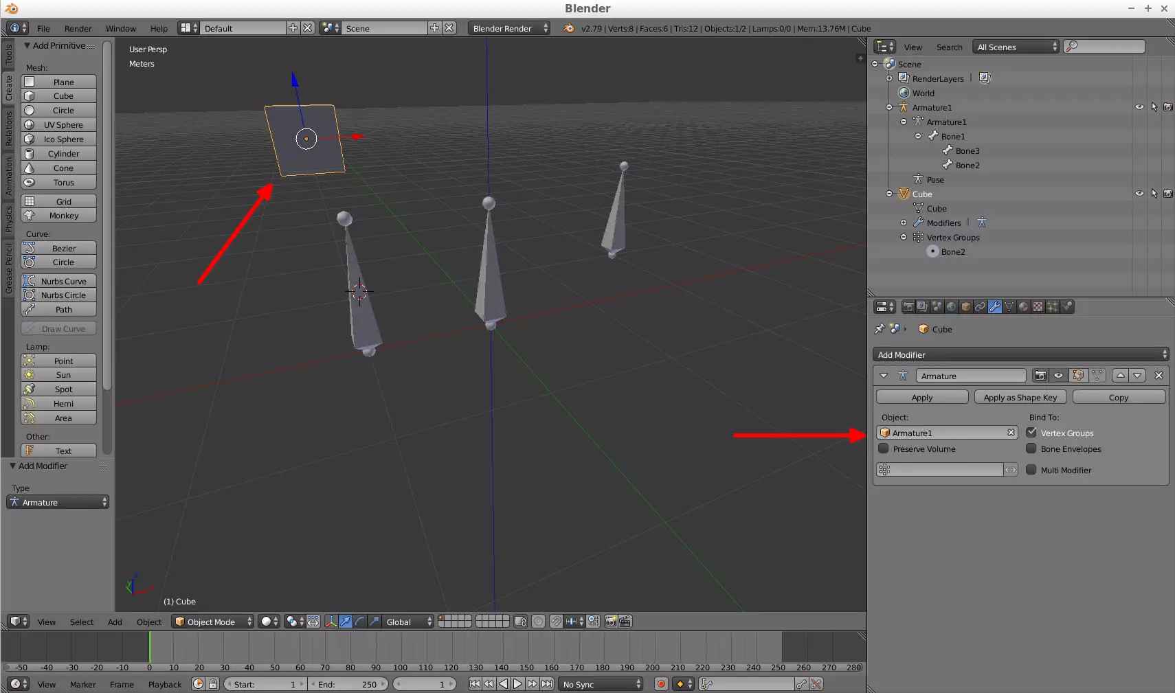
(Fig. 9 - Assigning vertex from mesh to vertex group)
Something else I want to add (I will explain it better later in the tutorial, with a failed attempt of my tutorial model) is that when making relative bones like this, you have to set their relative position with respect to the parent bone on the j3d-animation-editor program (on Frame 0) since for some reason when the model is converted to a BMD/BDL the relative bones will have the same location as its parent bone (this can get messy on complex animations).
Steps files used: tutorial10.zip
This tutorial is an example of what you can do, I can't cover it in a general way (because I am also new to this) and also can't describe everything I do, but I hope this example fits the explanation well.
I will make a car model. It has 4 wheels, and a propeller (because why not, Fig. 10).
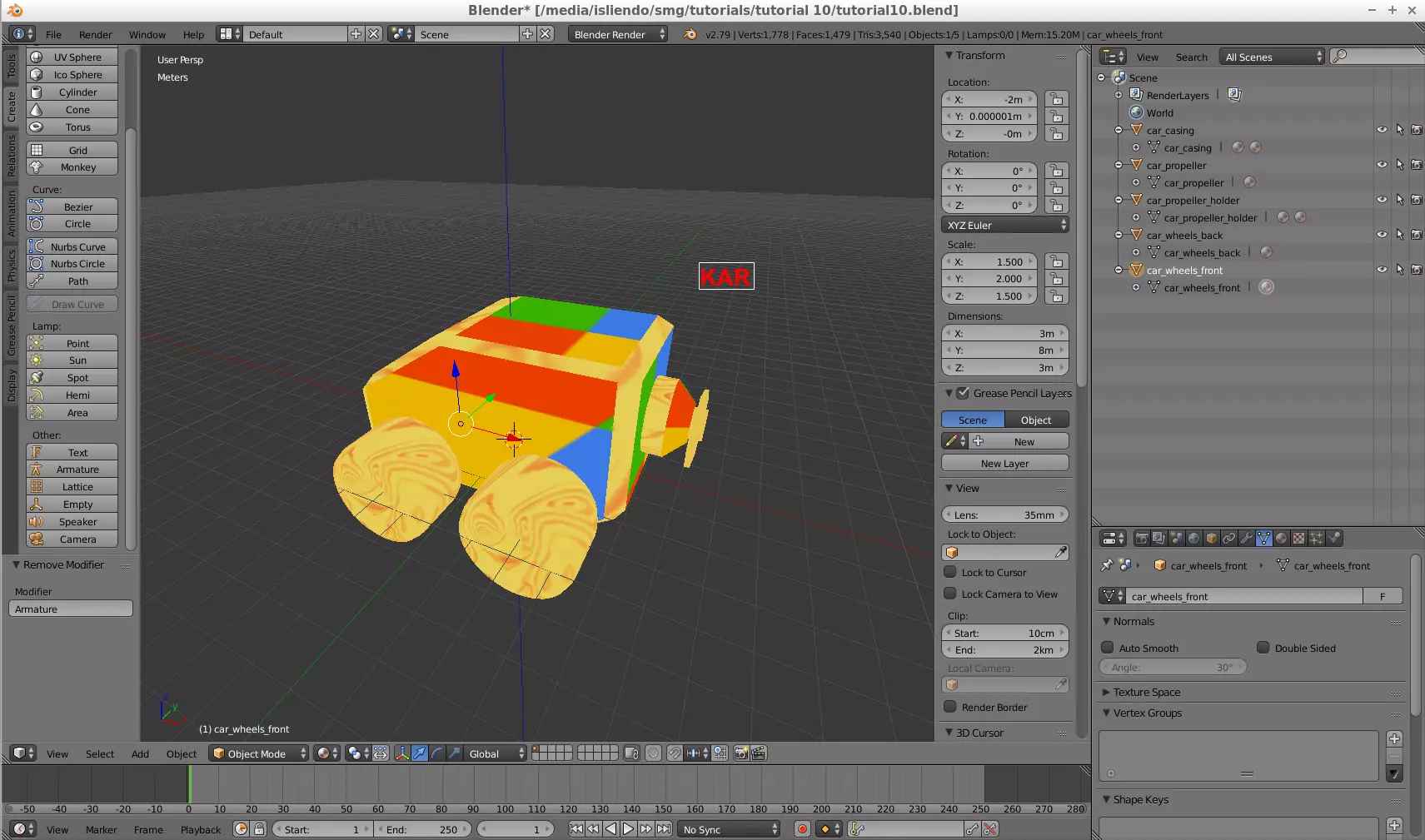
(Fig. 10 - Car model)
The model, as you can tell from Fig. 10, is divided in 5 meshes: car_casing, car_propeller, car_propeller_holder, car_wheels_back and car_wheels_front. The car_casing and car_propeller_holder will be assigned to the main bone and the others to a different bone each that will be child of the main bone. In total, the Armature object for this model will have 4 bones.
So let's create an Armature object that has this structure. Following what I've said above (pre-tutorial) we get something as shown on Fig. 11. I took the freedom to change each bone's name to a name I can understand its purpose.
(Fig. 11 - Armature object for car model)
The car bone, as it is the main bone, I can position it wherever I want to be honest so I will put it in the middle of the car model (Fig. 12).
(Fig. 12 - car bone location)
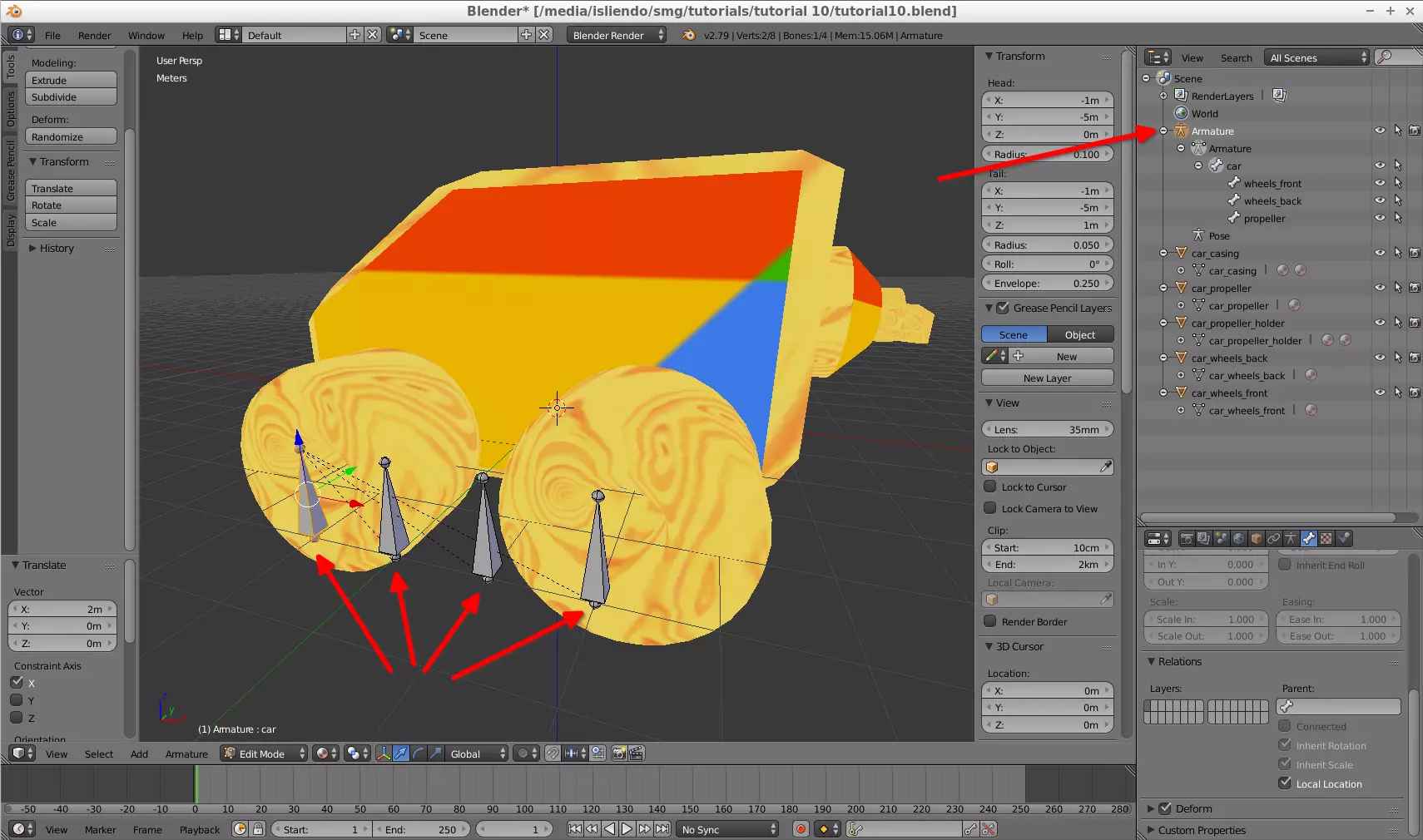
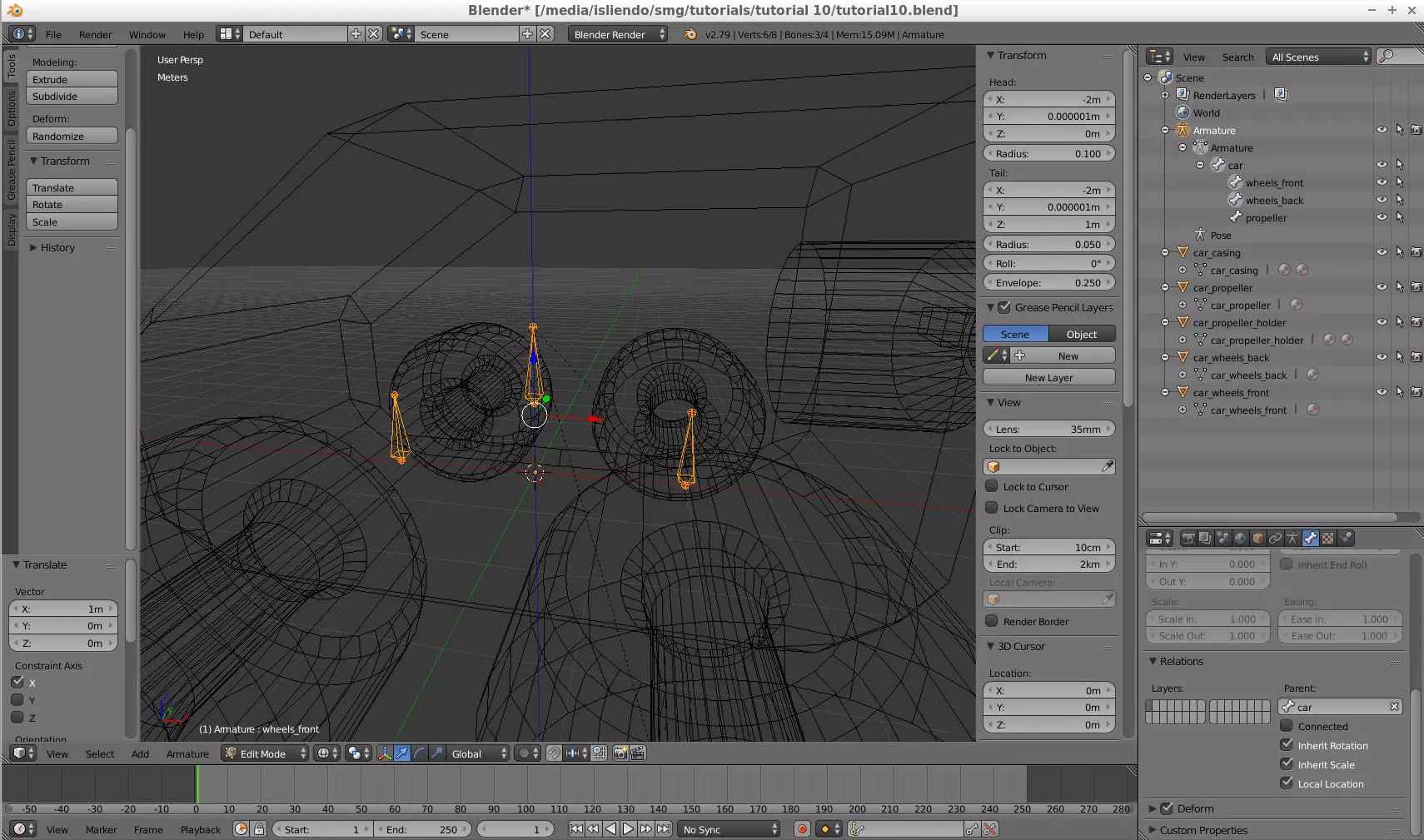
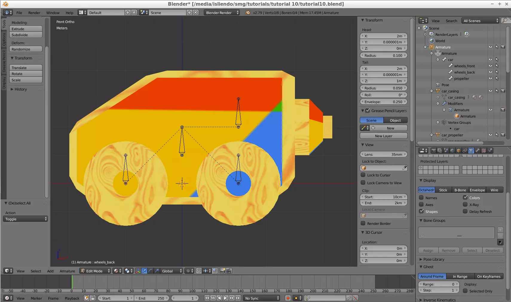
The wheels_front bone, as it is the bone for the front wheels mesh, I need to put it in the middle of the segment that connects both front wheel's centers (Fig. 13).
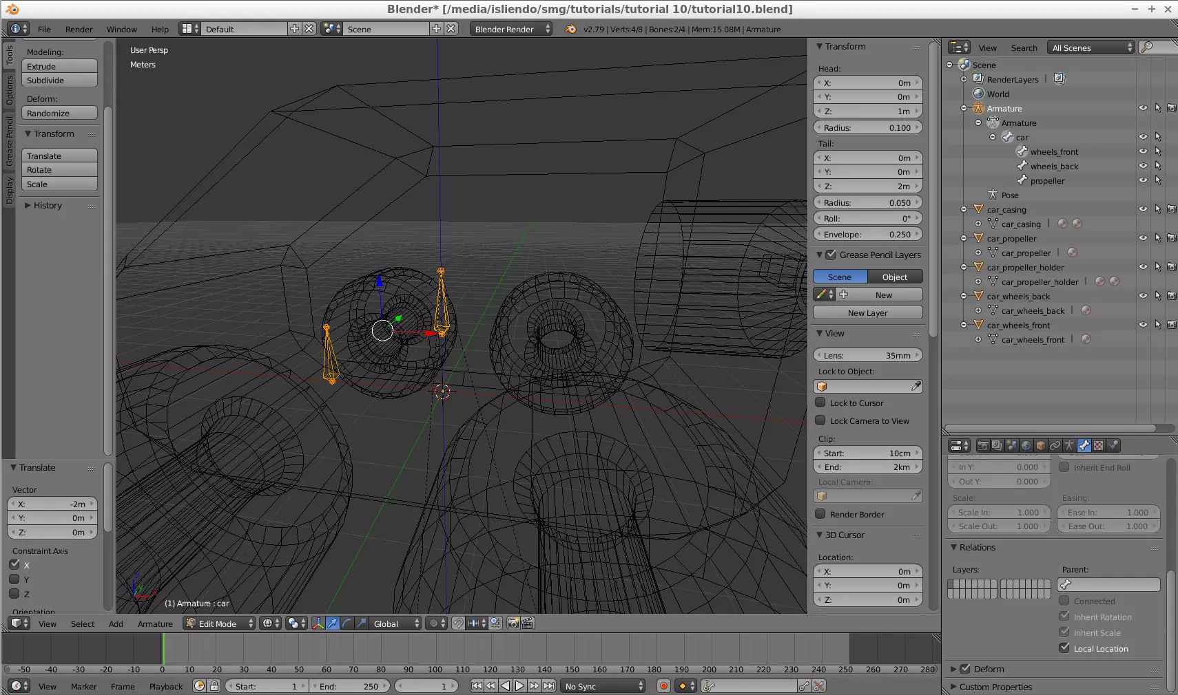
(Fig. 13 - wheels_front bone location)
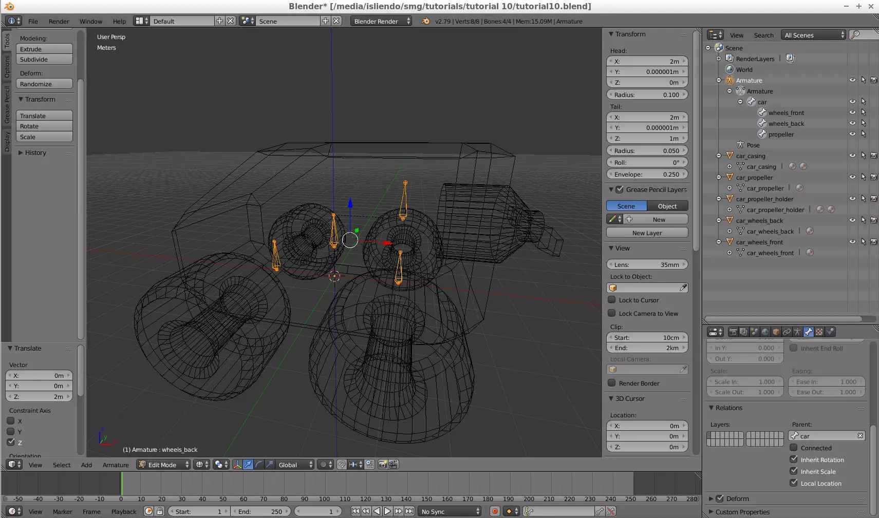
The wheels_back bone, as it is the bone for the back wheels mesh, I need to put it in the middle of the segment that connects both back wheel's centers (Fig. 14).
(Fig. 14 - wheels_back bone location)
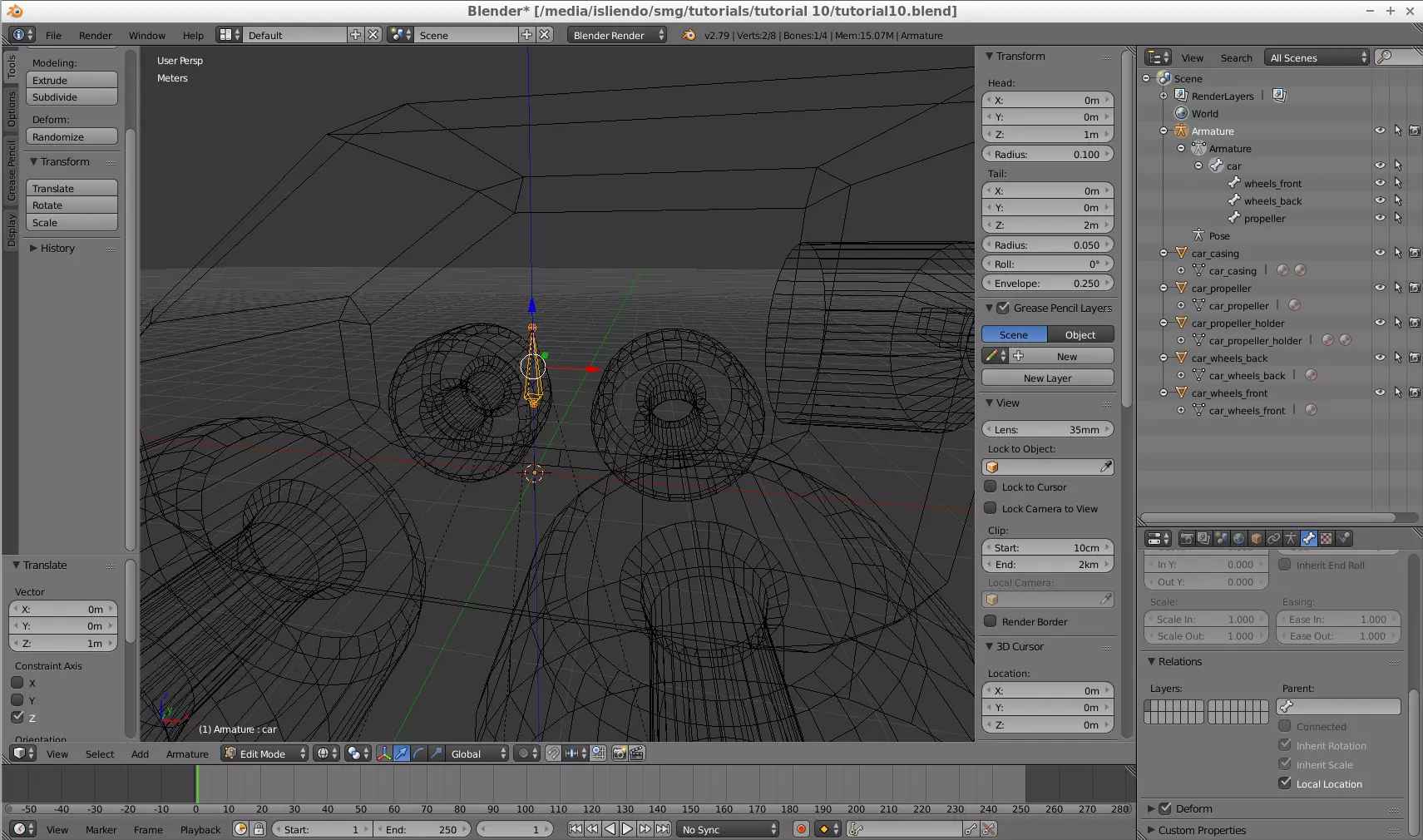
The propeller bone, as it is the bone for the propeller mesh, I need to put it in the line around which the propeller rotates (Fig. 15).
(Fig. 15 - propeller bone location)
After setting their positions exit Edit Mode and reset the Armature's position with Ctrl + A > Location so that the origin of the armature object is set to the origin of Blender's reference system (Fig. 16). You can also see on Fig. 16 how the bones are linked to each other (pretty cool huh).
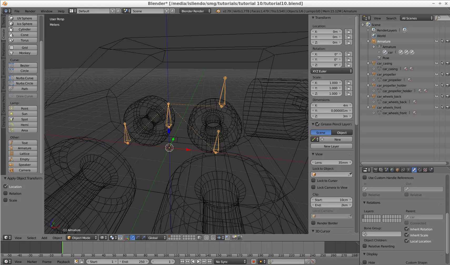
(Fig. 16 - Armature's new origin)
Set the armature object as the parent of all meshes and assign to all meshes the armature modifier with their Object property being the armature object (almost forgot this one lol - Fig. 17).
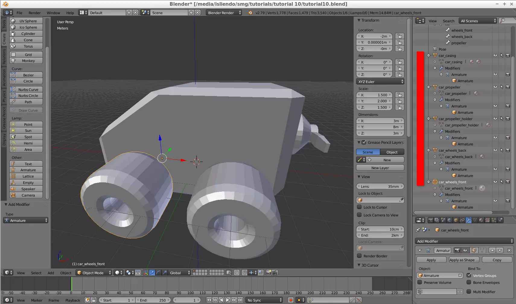
(Fig. 17 - All meshes with their Armature modifier)
With everything in its place, link/assign each mesh of your model to each vertex group needed. The car_casing and car_propeller_holder meshes to the car vertex group (Fig. 18 and 19), the car_wheels_back mesh to the wheels_back vertex group (Fig. 20), the car_wheels_front mesh to the wheels_front vertex group (Fig. 21) and the car_propeller mesh to the propeller vertex group (Fig. 22).
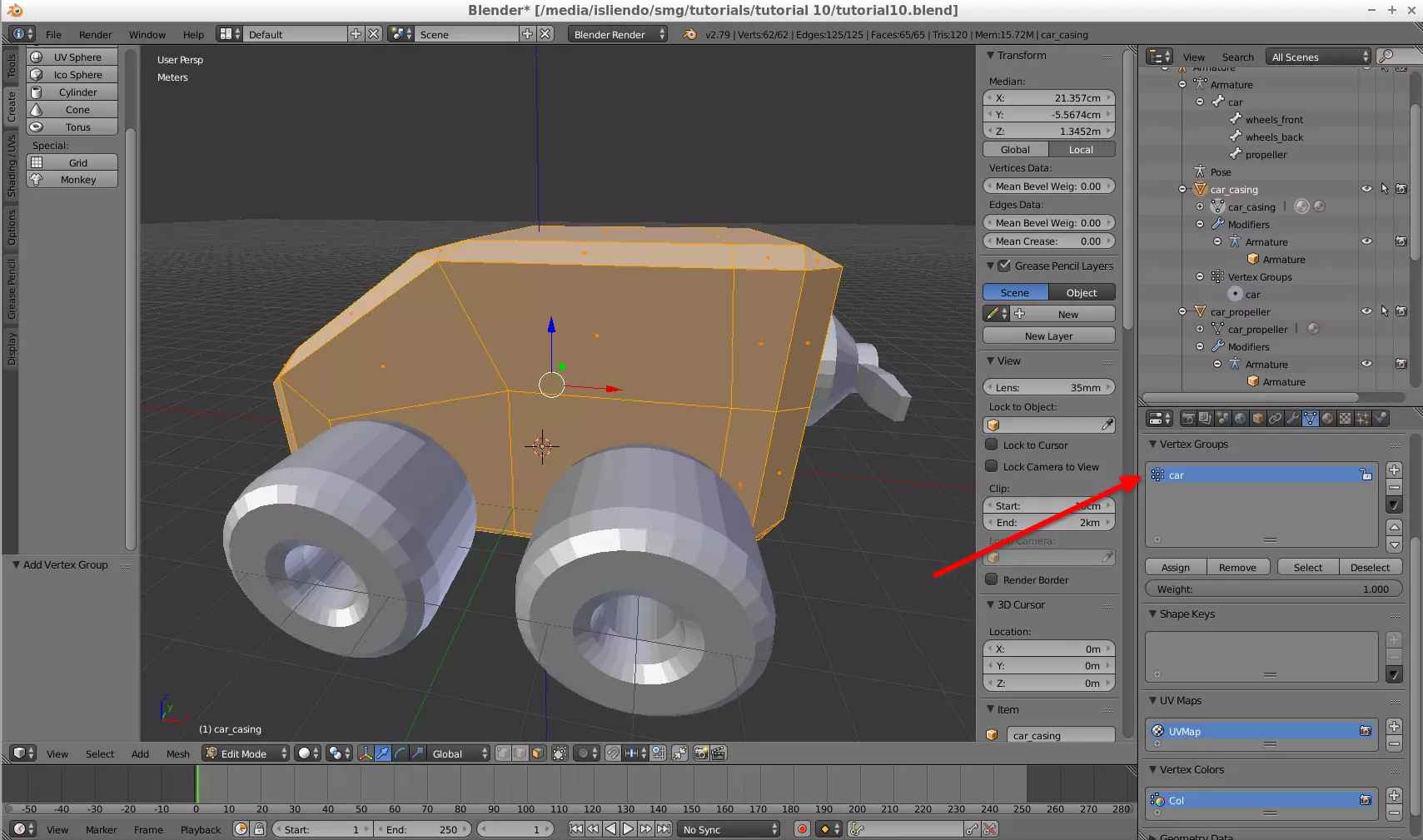
(Fig. 18 - car_casing assigned to car vertex group)
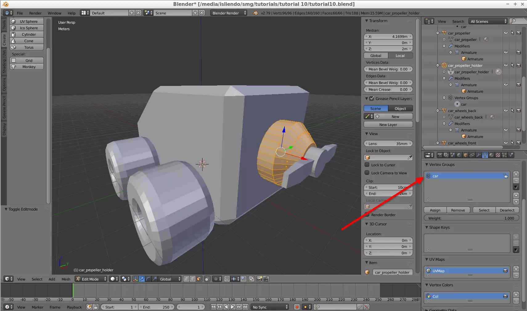
(Fig. 19 - car_propeller_holder assigned to car vertex group)
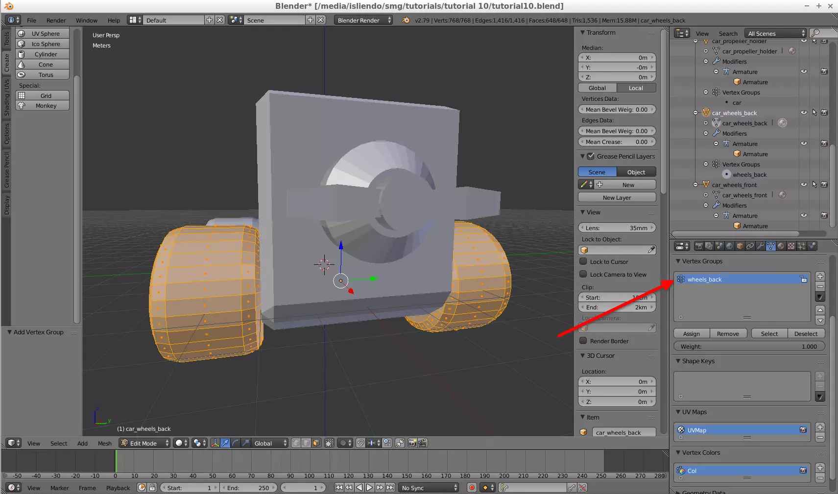
(Fig. 20 - car_wheels_back assigned to wheels_back vertex group)
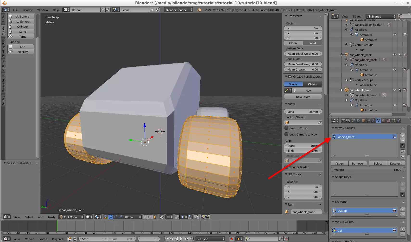
(Fig. 21 - car_wheels_front assigned to wheels_front vertex group)
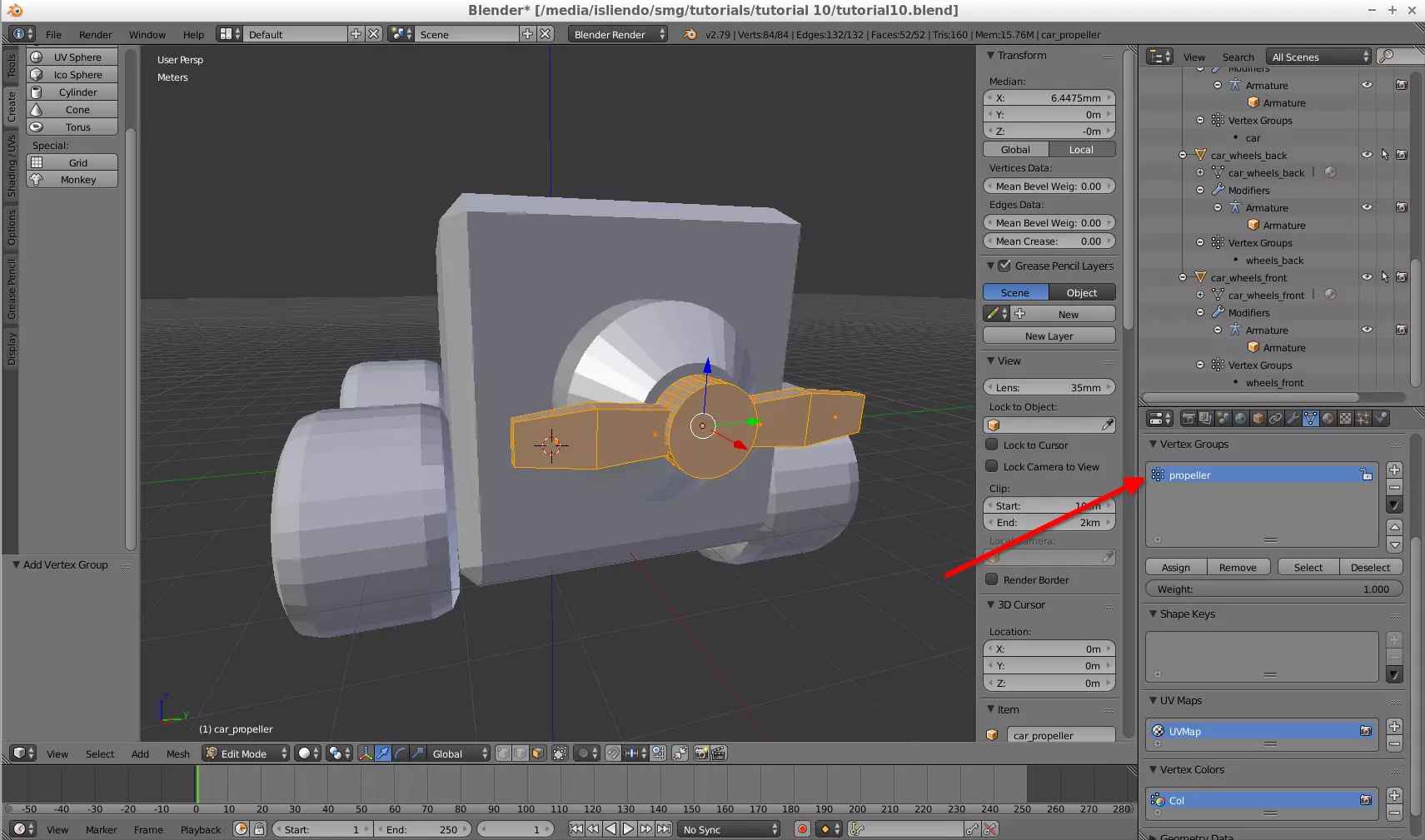
(Fig. 22 - car_propeller assigned to propeller vertex group)
NOTE 1: I had reset the positions of the meshes linked to the main bone with Ctrl + A. For some reason the model was converted weirdly if I didn't do it. Be careful with that stuff!
Now your model is ready to leave Blender! export it as an FBX (uncheck the Add Leaf Bones option of the Armatures Tab when exporting - Fig. 23).
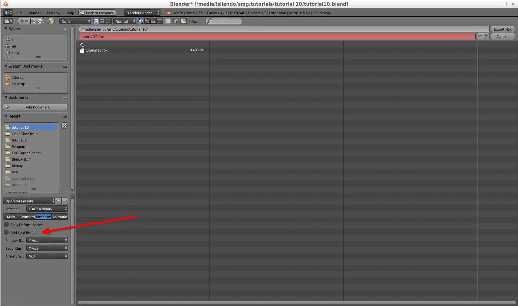
(Fig. 23 - Add Leaf Bones option unchecked on export)
NOTE 2: you can also export it as a DAE file without any more operations.
Then, convert the FBX to BMD with SuperBMD using the following command:
path\to\SuperBMD.exe [FBX model] --mat [Material JSON] --texheader [Textures JSON] --rotate --root_marker [Armature name] --nosort
Check the model on j3dview to see if everything looks correct (the rotations wont be so don't worry about that, the animation will fix it - Fig. 24).
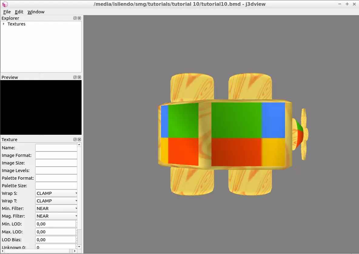
(Fig. 24 - Car model on j3dview, noice)
Now it begins the part of the jd3-animation-editor program. As the model has 4 bones create a new animation table on j3d-animation-editor that is 4 bones long (Fig. 25).

(Fig. 25 - New animation table for 4 bones)
As order of appearance, Joint 0 will be the car bone, Joint 1 will be the wheels_front bone, Joint 2 will be the wheels_back bone and Joint 3 will be the propeller bone. I will set the values for my animation as follows:
For the car bone: this bone will translate on the X axis only.
For the wheels_front bone: this bone will rotate around the Z axis.
For the wheels_back bone: this bone will rotate around the Z axis.
For the propeller bone: this bone will rotate around the X axis.
This animation will be in a loop and will last 200 frames.
NOTE 3: to understand how the rotations/translations/scaling work, you need to either use Whitehole and Blender to predict which will be the axis to assign the values or you can just brute force the values (assign values randomly) and test (in both cases) the animation for your object on j3dview.
With that, I get something as shown on Fig. 26.

(Fig. 26 - Animation table for car model)
At this point everything seems to be finished, but there is something else. It is what I mentioned on the beginning of the tutorial, the relative positions between bones. If I go and test my model with this animation I will get what is shown on Vid. 1.
(Vid. 1 - Car model with incomplete animation table)
All the relative bones are in the same position as the car bone! (see Fig. 27 as reference) To fix this you have to assign the relative position of each bone with respect to its parent bone on the Frame 0 of the animation table (you'll have to see and analize those positions from Blender, and remember, relative positions!).
(Fig. 27 - Bones position on Blender model)
On my Blenxy template one unit (Galaxy Unit or GU) is 100 units on the j3d-animation-editor program. The animation table, then, will look like what is shown on Fig. 28.
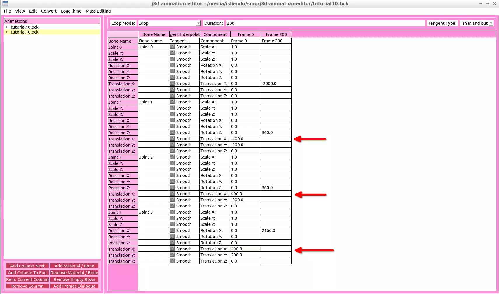
(Fig. 28 - Fixed animation table for car model)
NOTE 4: to avoid assigning Frame 0 values to a bone you want to animate, you can create 2 bones, let one be the child of the other, and, set the Frame 0 values to the parent bone, then the child bone will just inherit those positions and you can freely assign Frame values on the child bone without having to consider its Frame 0 values.
And then, the final result will be what is shown on Vid. 2 (finally!).
(Vid. 2 - Car model with correct animation table)
You can know do what you know to get the model on game C:
NOTE 5: if your model is too big the animations on game will look in like 1 FPS (it happened to me on this model). Be sure to scale the model down and apply Ctrl + A to it on Blender (scale down the Armature object and Ctrl + A everything that changes its scaling) as well as modifying the animation table according to the down scaling made.